 EN

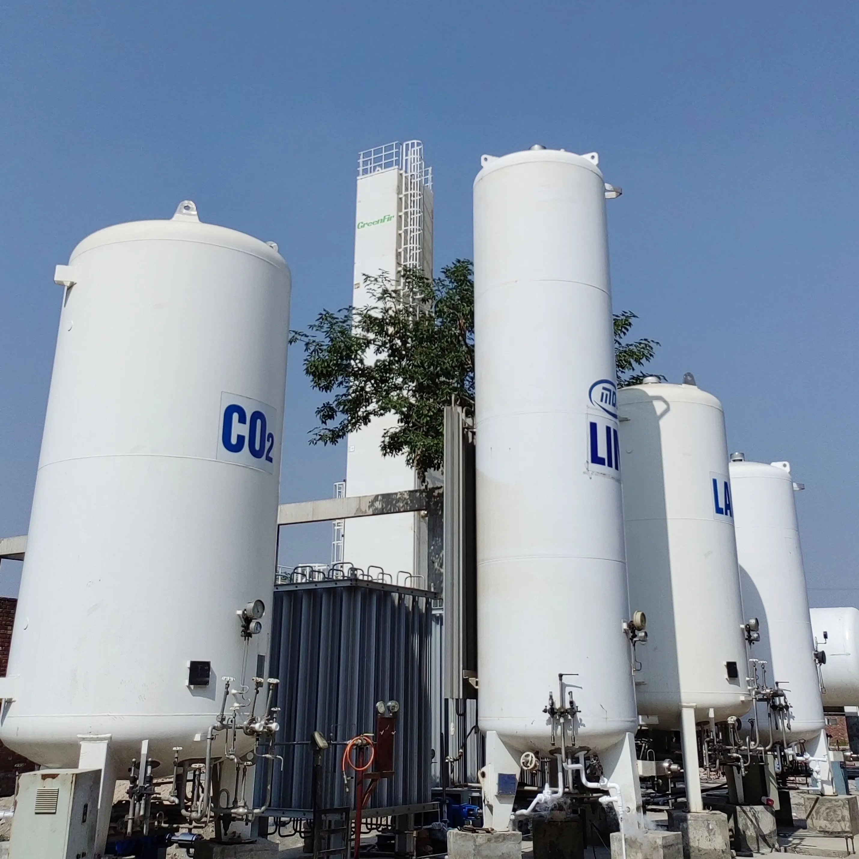
A small scale LNG plant looks deceptively simple on a process flow diagram. Gas comes in, gets cleaned up, gets cold, comes out as liquid. The block flow logic is clean. The execution is where projects go sideways.
The difference between a plant that ramps to nameplate and one that limps through its first year usually traces back to decisions made long before steel was cut. The liquefaction cycle chosen. The way feed gas variability was modeled. Whether the plant was designed as a stick-built site or a modular unit that had to survive a road trip. These are not abstract engineering preferences. They are the difference between a project that works and one that becomes a cautionary tale.
The liquefaction cycle choice is not a coin flip
Most small scale LNG plant designs come down to two refrigeration architectures: single mixed refrigerant (SMR) and nitrogen expander. On a simplified process diagram, both can liquefy gas. In the field, they behave very differently.
SMR circulates a mixture of refrigerants, typically methane, ethane, propane, and nitrogen, through a single compression train. The mixed refrigerant boiling curve can be shaped to match the cooling curve of natural gas fairly closely, which keeps thermodynamic irreversibility low. The trade-off is complexity. Refrigerant composition has to be managed and adjusted when feed gas conditions shift. The separator and fractionation system adds equipment count.
Nitrogen expander uses nitrogen as the working fluid, compressed and expanded through a turboexpander to produce cold. It is mechanically simpler. No refrigerant makeup, no composition control, no flammable refrigerant inventory. The penalty shows up at the power meter: published comparisons put nitrogen expander cycles at roughly 30 percent higher power consumption than SMR under comparable conditions, and one economic analysis found mixed refrigerant energy consumption at roughly 46 percent of the nitrogen expander cycle. For a plant paying industrial electricity rates, that gap compounds over years of operation.
The choice rarely rests on efficiency alone. Grid reliability, operator skill level, and whether the feed gas composition is stable or moves around week to week all push the decision in different directions. A remote site with unstable power and limited technical staff may accept the efficiency penalty for the operational simplicity of a nitrogen cycle. A plant tied to a stable utility grid and a consistent pipeline feed can capture the SMR advantage. Neither answer is universally correct.
Feed gas variability is where design margins earn their keep
Small scale LNG plants frequently sit downstream of gas sources that would never pass a pipeline quality spec without treatment, or that vary in composition in ways a design basis document cannot fully anticipate. Associated gas from oil production, coalbed methane, biogas-derived streams, and stranded gas from marginal wells all bring their own fingerprints.
A 2025 study evaluating four liquefaction configurations against multiple feedstocks found that SMR, nitrogen expander, and dual mixed refrigerant processes could adapt to both heavy and light feedstocks within fixed design constraints. The mixed fluid cascade configuration, by contrast, struggled with light feedstocks because of inadequate heat transfer capacity. That finding matters for design engineers because it shows that the “high efficiency” option on paper is not automatically the flexible option in practice.
Heavy hydrocarbons are the other side of the coin. A gas stream with meaningful propane and butane content will not liquefy cleanly without a scrubber or fractionation step upstream. If those heavy ends carry value as NGL or LPG, recovering them can improve project economics. If they are simply a nuisance, they have to be removed and disposed of safely. Pretreatment design, dehydration, mercury removal, and heavy hydrocarbon removal, consumes a larger share of the plot plan and the capital budget than the liquefaction cold box itself in many projects. Treating pretreatment as a secondary concern is a reliable way to discover, during commissioning, that the cold box is being asked to handle a feed it was never designed for.
Modular design is a logistics problem before it is an engineering problem
The modular promise is straightforward: fabricate the plant in a controlled shop, test it, ship it as skids, bolt it together on site. The execution is less straightforward.
A skid that meets the dimensional limits of a standard truck or container is a different engineering object from a site-built cold box. Heat exchanger selection shifts toward compact brazed aluminum plate-fin units because plot space is constrained and structural steel has to be minimized. Piping layouts have to survive transport-induced vibration and lifting loads. The structural frame itself is not just a support system. It is a shipping container.
Consider a 120,000 tonne-per-year modular liquefaction unit destined for a gas field in western Canada. The design team specified a brazed aluminum cold box sized for transport on a standard multi-axle trailer. During fabrication, the cold box passed pressure and leak testing at the shop. On arrival, the site crew discovered that the transport route included two bridge weight restrictions that forced a last-minute re-routing and a nine-day delay. The skid was fine. The logistics plan was not. That kind of sequence, where the equipment is ready but cannot reach the site, is a recurring pattern in modular project post-mortems. Early transport route surveys, lifting studies, and module weight verification belong in the design phase, not the shipping phase.
For plants at the smaller end of the range, the modular approach can compress field construction timelines significantly. Chinese fabrication experience with skid-mounted LNG units has shown site construction periods cut by more than half compared with conventional stick-built plants, largely because welding, pressure testing, and instrumentation loops are completed and verified in the shop. That schedule advantage is real, but it depends on the module being designed for transport from day one, not adapted for it after the fabrication drawings are frozen.
Standards compliance means tracing the weld, not listing the certificate
ASME Boiler and Pressure Vessel Code Section VIII Division 1 governs the design and fabrication of the pressure vessels that contain cryogenic fluids. For LNG service, the material specifications matter as much as the design equations. Impact testing requirements for low-temperature toughness, welding procedure qualifications under Section IX, and post-weld heat treatment where applicable all sit behind the U-Stamp on the nameplate.
API Standard 620 covers large welded low-pressure storage tanks, including those in cryogenic service, and sets requirements for design, materials, construction, inspection, and testing. A small scale LNG plant may not use a large field-erected storage tank, but the same design philosophy, secondary containment, pressure relief sizing, and cold spill protection, carries over to the storage and send-out portion of the facility.
The gap between a supplier that holds the certificate and one that operates under the certificate shows up in records. Can the fabricator trace a specific weld on a cold box nozzle back to the individual welder who made it, the procedure specification used, and the radiographic or ultrasonic test results for that joint? Can the material test reports for the low-temperature steel plate be matched to the heat numbers on the vessels? These questions are answerable if the quality system is running. They are not answerable if the quality system is a binder assembled for the audit.
The cost conversation that starts before the first quote
Published benchmarks for small scale liquefaction capital costs vary widely because the scope varies widely. The Union for the Mediterranean puts gas platform investment for small scale liquefaction terminals in the range of 350 to 1,250 USD per tonne of annual capacity, a spread that reflects differences in technology, modularity, and site conditions. A separate industry analysis notes that sub-1 MTPA plants face unit capital and fixed operating costs 50 to 100 percent higher than large scale LNG, which is the structural penalty for giving up economies of scale.
Those numbers are useful for early-stage screening, not for budgeting a specific project. The variables that move the number most are pretreatment scope, storage capacity, power supply, and the degree of modularization. A plant with a clean pipeline-quality feed and a short tie-in to the grid is a different capital animal from a plant handling sour associated gas at a remote site with diesel-generated power.
| Decision area | SMR cycle pattern | Nitrogen expander pattern | What it changes downstream |
|---|---|---|---|
| Refrigerant management | Mixed refrigerant makeup and composition control required | No refrigerant inventory, dry nitrogen only | Operator training and spare parts strategy |
| Power consumption | Lower compression power per tonne of LNG | Roughly 30 percent higher power draw than SMR | Operating cost exposure and generator sizing |
| Feedstock flexibility | Adapts to heavy and light feedstocks within fixed design | Adapts to heavy and light feedstocks within fixed design | Pretreatment scope can stay stable across gas sources |
| Mechanical complexity | More equipment, more control loops | Fewer rotating parts, simpler control philosophy | Maintenance staffing and remote monitoring design |
| Modular transport impact | Larger cold box and compression skid footprint | Smaller, lighter modules in some configurations | Route surveys and lifting plans |
A practical way to use this comparison is to treat the cycle selection as a project-specific trade study, not a default. The lowest-efficiency option can be the right answer if it removes a failure mode the site cannot manage. The highest-efficiency option can be the wrong answer if the feed gas will change and the operator cannot adjust refrigerant composition on the fly.
Where manufacturing integration changes the design conversation
Jianyang Greenfir New Energy Equipment builds small scale LNG plants and modular LNG skids from a manufacturing base in Sichuan, covering liquefaction capacities from roughly 1 to 20 MMSCFD and integrating pretreatment, cold box, and controls into transportable modules. The engineering and fabrication sit under one roof, which matters when the cold box dimensions, the skid weight, and the transport envelope have to be reconciled early rather than discovered late.
For a design team working through the trade-offs above, that integration shortens the loop between process simulation and what can actually be built, shipped, and commissioned. The conversation can move past catalog capacities and into the specific gas composition, site power profile, and module logistics that determine whether a small scale LNG plant performs as designed or becomes a collection of equipment waiting for the next change order.
Table of Contents
- The liquefaction cycle choice is not a coin flip
- Feed gas variability is where design margins earn their keep
- Modular design is a logistics problem before it is an engineering problem
- Standards compliance means tracing the weld, not listing the certificate
- The cost conversation that starts before the first quote
- Where manufacturing integration changes the design conversation