 EN

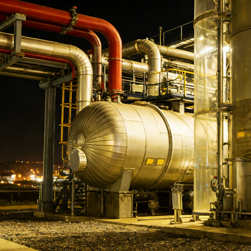
Cryogenic technology in natural gas liquefaction turns pipeline-quality natural gas into liquefied natural gas by dropping feed gas temperature close to -162°C at ambient pressure. This phase change shrinks gas volume drastically and enables long-distance transport without fixed pipeline infrastructure. Every reliable liquefaction train depends on matched cryogenic hardware, refrigerant selection and tight process control, and small deviations in thermal balance can drag down throughput or trigger stability issues.
Pre-treatment Steps That Set Up Cryogenic Performance
Raw natural gas carries water, carbon dioxide, hydrogen sulfide and heavy hydrocarbons. These contaminants create solid deposits inside cold boxes and heat exchangers once the stream enters low-temperature zones. Even trace water can form hydrates and block narrow flow channels, while carbon dioxide freezes into dry ice and fouls plate-fin exchangers.
- Dehydration removes water vapor down to extremely low residual levels.
- Acid gas sweetening strips CO₂ and H₂S to meet cryogenic feed specifications.
- Heavy hydrocarbon separation extracts C5+ fractions before cooling starts. ISO 20257-1:2020 sets baseline design rules for LNG facilities and defines acceptable impurity thresholds ahead of cryogenic sections, as untreated feed will quickly lead to unplanned shutdowns. Operators often overlook this link, treating purification and liquefaction as separate blocks, but cryogenic performance lives or dies by inlet gas quality.
Core Cryogenic Cycles Used for Natural Gas Liquefaction
Most commercial liquefaction units run on one of four mature cryogenic cycles. Each cycle balances energy draw, equipment footprint and operational flexibility, and no single design fits all site conditions.
| Process Type | Relative Energy Efficiency | Footprint & Complexity | Best Fit Scenario |
|---|---|---|---|
| C3MR (Propane Precooled Mixed Refrigerant) | High | Medium | Mid-to-large onshore LNG trains |
| DMR (Dual Mixed Refrigerant) | Very High | High | Large base-load plants |
| SMR (Single Mixed Refrigerant) | Moderate | Low | Small-scale modular skids |
| Nitrogen Expander Cycle | Low | Low | Remote or offshore compact units |
C3MR remains the dominant choice across global midstream projects. It uses propane to pull the feed stream down to roughly -35°C, then a multicomponent mixed refrigerant delivers further cooling until liquefaction completes. DMR removes the pure propane loop and uses two mixed refrigerant circuits for tighter thermal matching, which cuts energy use but adds compressor and control hardware. SMR runs only one refrigerant loop and simplifies layout, though its power demand climbs under variable feed composition. Nitrogen expander cycles avoid hydrocarbon refrigerants entirely and tolerate motion, which works well for floating installations, but running costs sit higher under steady full-load operation.
Field Observation of Cryogenic Heat Exchanger Degradation
During a retrofit project at an inland gas processing site, operators noticed gradual LNG output drop over three months while all sensor readings stayed within nominal ranges. Inspections after shutdown found uneven refrigerant distribution inside the main cold box. Minor accumulation of heavy fraction sludge blocked partial passages, creating thermal maldistribution across the exchanger core. The unit did not trip on alarms, but the cryogenic temperature profile drifted away from design curves, reducing effective heat transfer area. This case drives home a simple lesson for cryogenic operation. Performance decay does not always show up as sudden trips. Periodic thermal profile logging and refrigerant composition testing catch slow degradation before capacity loss becomes severe. Mixed refrigerant composition drift is one of the top hidden drivers of poor liquefaction efficiency in long-run facilities.
Practical Limitations of Cryogenic Liquefaction Systems
Cryogenic liquefaction carries inherent constraints that cannot be engineered away completely. The process consumes a share of feed gas as fuel for compression and refrigeration drivers, and this energy penalty stays meaningful regardless of cycle optimization. Materials also need careful selection for cryogenic service. Standard carbon steel loses ductility sharply below -40°C, so heat exchangers, piping and valves must use low-temperature alloy materials to resist brittle fracture. Load flexibility forms another hard boundary. Large cryogenic trains are built for stable steady-state operation. Frequent turndown swings shift refrigerant loading and pinch points, raising the risk of liquid carryover into expanders or compressors. Many small-scale skids handle load changes more gracefully, but they cannot match the unit cost advantage of large base-load trains running at constant rates.
Refrigerant Tuning and Operational Fine-Tuning
Refrigerant blend tuning is where experienced process teams separate stable liquefaction from unreliable runs. Mixed refrigerant contains nitrogen, methane, ethane and propane, and the proportion of each component shapes how closely the cooling curve matches the natural gas cooling profile. A well-tuned blend keeps temperature differences across the heat exchanger low and reduces exergy loss. Tuning is not a one-time task after commissioning. Feed gas composition shifts with well output, ambient temperature changes with seasons, and minor refrigerant losses during maintenance alter the blend. Regular sampling and controlled makeup restore thermal matching without full system shutdown. Operators who skip scheduled refrigerant analysis usually see slow rises in specific power and unstable LNG subcooling.
Greenfir delivers robust cryogenic equipment packages built against rigorous process standards, with tight fabrication control for heat transfer components and pressure boundary parts. Its supply chain supports modular assembly and site-adapted packaging for different liquefaction layouts, giving project teams reliable hardware to execute cryogenic natural gas liquefaction designs.